Buying a new AP to cover more space
So I recently moved to a new flat. This was a significant upgrade for me, since before I was living in almost 40m2 and a single AP was enough.
However, once I moved to almost 80m2 - it turns out single AP cannot cover 5GHz for the whole flat, so I had to buy another one.
I wanted to buy something cheap & reliable. I came across TP-Link RE650 recommendation somewhere on the internet, it was quite cheap and promised high speed so I said why not.
Before I did that, I checked that it is supported by offical build of OpenWrt, seen here: https://openwrt.org/toh/tp-link/re650_v1.
Recieving the package
Once I recieved the package, it turned out that the device is V2 version of that model, instead of the v1 which is officially supported.
However, it looked almost identical to the v1 (and on OEM site it is listed under same page), so I wondered - how can I OpenWrt build for it?
Searching for information
There is a topic on OpenWrt forum about v2 of this device. However, they also say that I cannot flash the v1 firmware on it, because apparently it has only 8MB of flash and it just won’t fit. The v1 version of it had 16MB of flash.
And that’s how my journey started.
How did I do it?
Before I start a disclaimer - I’ve never done such thing before. I’m barely an electronics hobbyist, and I’ve a few things in my inventory that happened to be helpful to do it (namely, the USB-Serial adapter and soldering iron).
So first thing that came to my mind, is to try to see how RE650 v1 was implemented in the openwrt code. For that, I cloned the github repository of it and just started a search for “RE650”.
It turnes out, that there was not much that it takes to add a support to the device (at least in TP-Link case). Someone already has done the majority of work for me, as you can see in this github commit
But I was really worried about bricking the device if I make a mistake, even though the device is really similar, I just wanted to confirm what it has inside of it, and build specifically for it.
What I needed to know is:
- Size of the flash memory
- What CPU does it have
- What WiFi chips does it have
- How is the flash partitioned
There were instructions on the RE650 v1 wiki page on how to connect to the serial port of the device, so I though why not give it a try.
Disassembly of the device
I won’t show you how I disassembled the device, however, I’d like to show you how it looked like after doing it:
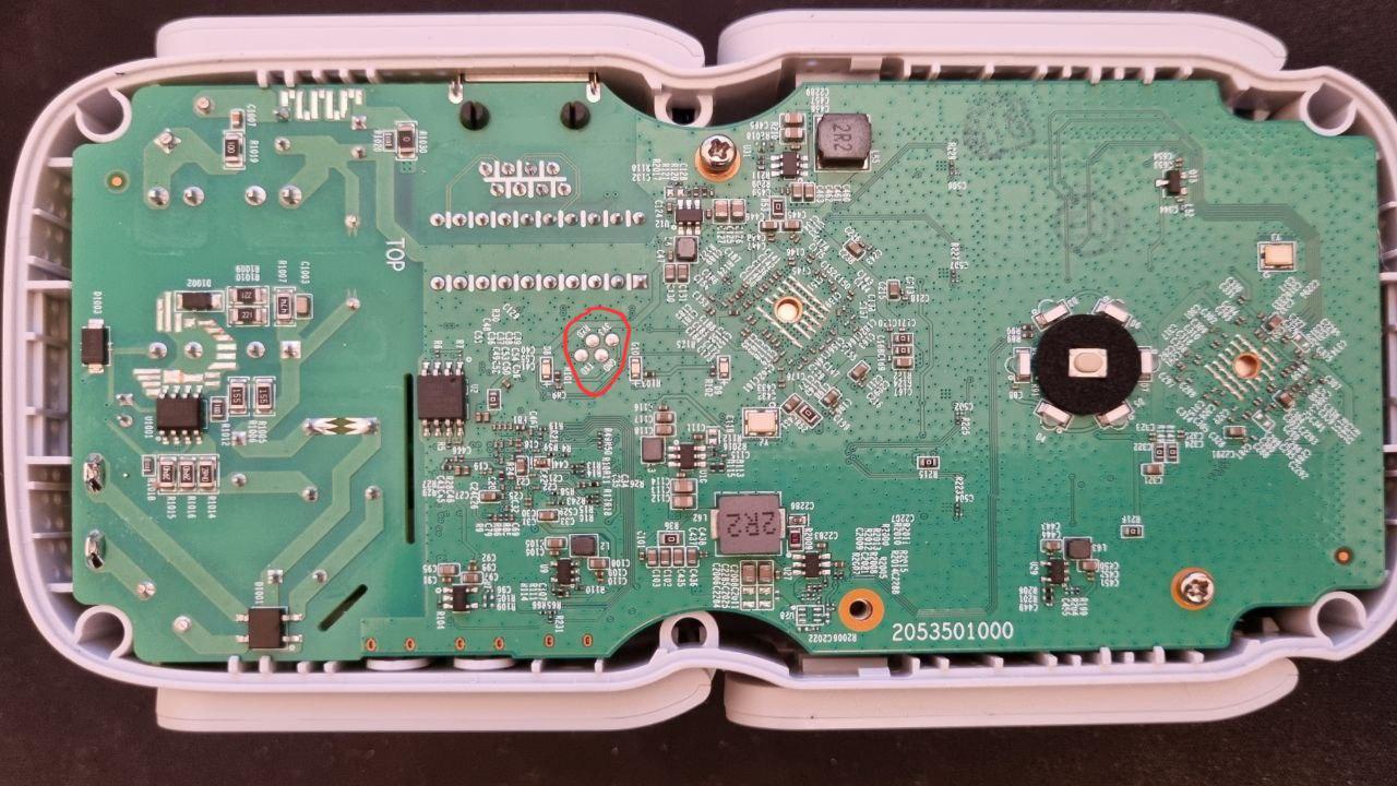
Board of the device
In the middle of it you can see circled in red - UART pinout. This is a serial interface to the CPU, which allows you to see what it says and do stuff with it.
Seeing that, I quickly jumped to soldering station and soldered cables to it.
Tips from hobbyist: If you’re soldering surface mounted pads, make sure that:
- You use the lowest temperature that allows you to solder (look up temperature for lead-free solder)
- You use a soldering tip with enough contact surface to transfer the heat (generally, bigger = better, but too big can be cumbersome to use)
- That you put enough solder flux on it before you start soldering (recommending flux in small syringe). There is no too much flux, you can always clean it up later with rubbing alcohol.
- Use wires which are pretty flexible and small enough
All these tips combined will minimize the ability for pads to get lifted from PCB, and possibly damaging the board.
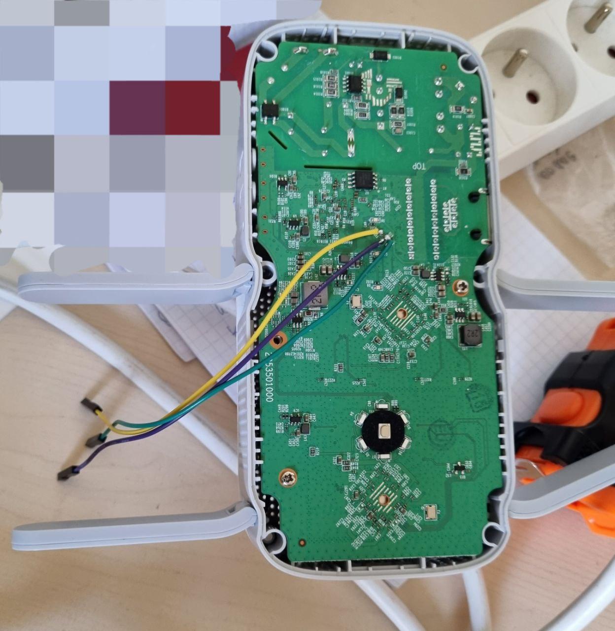
Jumper wires soldered to UART
WARNING: This device is plugged directly to the power outlet. Don’t do it at your own, unless you know what you’re doing and know how to protect yourself from electrocution. Because AC to DC is on the same board as the device itself, there is high voltage in there that can potentially be lethal to you. It’s much safer when the device has dedicated power brick.
Saying that, I used jumper wires with female ending, because my USB-to-Serial has male pinout.
I’ve left out the 3v3 pin, and only soldered TX/RX/GND as per instructions on OpenWrt
I connected USB Serial to the board and the computer, I powered the board aaand…
USB-to-Serial was interrupting start up of the device
When I connected all three wires (GND->GND, RX->TX, TX->RX), the device didn’t want to boot. Turns out, there is not enough resistance between RX/TX of my converter and the device, and the little current that was flowing from my computer to the device was putting the device in some undefined state.
I just had to leave out the RX of the device disconnected when I boot it, and I could reconnect it back on once it’s booted. RX is used to recieve commands from my computer, so I could still see everything since I had TX still connected.
I’ve used picocom with the command picocom -b 57600 /dev/ttyUSB0
Before my eyes unleashed everything the device wanted to tell me.
Getting root access
Well, this could’ve been a story about how my advanced hacking skills allowed me to hack into the device and gain access through some obscure 0-day.
However, all it tooks is hitting “Enter” in the terminal.
It turns out, TP-Link’s firmware is based on some old OpenWrt version (13.0x something?) And they generally leave root logged in on the serial.
Dumping the firmware
First things first, it’s generally a good idea to dump the firmware that your specific device has, fully, to some other place.
You don’t want to risk bricking it, without having some sort of backup.
Device’s like this one, use flash directly through so-called “mtd”.
To list available “partitions”, you have to run cat /proc/mtd
You’ll get output similar to this one:
# cat /proc/mtd
dev:    size   erasesize  name
mtd0: 00020000 00010000 "u-boot"
mtd1: 007a0000 00010000 "firmware"
mtd2: 002455dc 00010000 "kernel"
mtd3: 0055aa24 00010000 "rootfs"
mtd4: 001c0000 00010000 "rootfs_data"
mtd5: 0002d440 00010000 "config"
mtd6: 00010000 00010000 "radio"
However, there is no guarantee that they’re not overlapping each other.. There could be (and it is a case here as well) that the kernel is inside of firmware partition, or part of it.
What you’ve to do is dump every single one of these (using dd or just cat /dev/mtd<x> >> mtd<x>.bin),
and copy them over to your computer (Since I had root access on the device itself,
I just scp’d it to my computer).
Looking at the firmware through hex viewer
Generally, it’s good idea to have a look at the firmware through hex editor. You will be able to spot, at least visually, some strings in it, that may be helpful to what you’re doing.
In my case, I found a partition table in it, which had laid out the structure of the flash chip:
partition fs-uboot base 0x00000 size 0x20000
partition os-image base 0x20000 size 0x330000
partition file-system base 0x350000 size 0x470000
partition partition-table base 0x7c0000 size 0x02000
partition default-mac base 0x7c2000 size 0x00020
partition pin base 0x7c2100 size 0x00020
partition product-info base 0x7c3100 size 0x01000
partition soft-version base 0x7c4200 size 0x01000
partition support-list base 0x7c5200 size 0x01000
partition profile base 0x7c6200 size 0x08000
partition config-info base 0x7ce200 size 0x00400
partition user-config base 0x7d0000 size 0x10000
partition default-config base 0x7e0000 size 0x10000
partition radio base 0x7f0000 size 0x10000
With that information at hand, filling out the blanks in the new device definition for the OpenWrt was easy. Since the RE650 v1 support flashing through OEM, I thought my device could do it as well!
Preparing the device definition in OpenWrt
After I’ve cloned the OpenWrt repository, I took a look again at the commit which defines the RE650 support, and I searched through the repo to find relevant files.
On openwrt-21.02 branch files that I had to modify were:
target/linux/ramips/mt7621/base-files/etc/board.d/01_leds- for LEDs definitionstarget/linux/ramips/mt7621/base-files/etc/board.d/02_network- for default network definitonstarget/linux/ramips/image/mt7621.mk- for the compilation targettools/firmware-utils/src/tplink-safeloader.c- for generating the binary that is compatible with OEM Web UI to be able to flash OpenWrt easily.target/linux/ramips/dts/mt7621_tplink_re650-v2.dts- a new device tree defintion that defines the concrete model of the device. Without that - you won’t be able to build image for that device.
Creating the device tree definition
Majority of the work has been done for RE650 v1, I barely copied that over for my device,
and I changed the definition at flash@0 to match what I found in the partition table.
Partition definitions consist of specifications of offset and size of the partition
in the following form: reg = <offset size>;, both defined in hex representation.
Noteworthy is that in the partition table, there are two parts of the firmware
image - os-image and file-system. In case of OpenWrt - they can be combined
assuming that they’re continuous block (i.e. after each other). Then it can be
used just as firmware partition. In my case, continuous block has had a
combined size of 0x7a0000 which equals around 7995KB. Just enough to fit
the stock image of OpenWrt.
I’ve marked all the partitions below file-system as read-only config in the
OpenWrt. Reason for that is we don’t want to override these, as if you decide
to go back to the OEM firmware - these might be essential for the functionality!
Last one important bit is radio partition, which contains calibration data
for the WiFi chips. This are essential to get right, otherwise your WiFi might
just not work correctly.
Generating the factory image
I won’t go into details of buidling OpenWrt, however, I think instructions on their wiki are pretty self explanatory and if you install all dependencies right, it should build easily.
How I do it specifically for myself:
- I checkout a specific branch (
openwrt-21.02in this case) - I apply changes to the files mentioned above
- I copy config.buildinfo as .config into my openwrt directory (from that release’s target, for example ramips 21.02 is here at the bottom)
- I run feeds update & install
- I run
make defconfigand thenmake menuconfig - In
menuconfigI select only my newly added board, and I make sure drivers inKernel Modules->Wireless Driversare selected, as per thetarget/linux/ramips/image/mt7621.mk(In my case, I have to selectkmod-mt7615e kmod-mt7615-firmwarepackages) - I run the rest of the targets (
download clean world)
Notable things to know:
- in
21.02, if your configuration creates image that is too large to fit the device (as specified in themt7621.mk), sysupgrade and factory images WON’T be generated. - Same happens if your device is not specified in
tplink-safeloader.ccorrectly - On master, if you don’t add
tplink-safeloader.centry, you will getwarning: image file is too bigBut it has nothing to do with the size, it’s generation of specific image that failed due to missing safeloader entry
What obstacles did I have
There are few things that I had pain with getting right. I spent almost 4 days, every evening trying to solve these, but in hindsight they were pretty obvious mistakes.
I was resorting to reverse engineering the OEM firmware and trying to make sense of it, but sometimes you just have to trust your gut and try few things which don’t make obvious sense
Can’t upload factory image through OEM UI
So I had a problem where factory image that I generated was not being accepted in the
OEM UI. I had copied the config exactly as for the v1, just for v2. It was just outright
denying the file that I put in there, without even attempting to process it.
It turned out that in the firmware that I had, I must add soft_ver string in tplink-safeloader.c,
which is higher than a current version. OEM UI was denying the firmware file I was
giving it, because it was probably assuming that I wanted to downgrade or something
and that was prohibited.
This is the error I was getting through the serial console:
_index() ................................. set_upgrade_fwup_flag 1591
set_upgrade_fwup_flag(): create /tmp/upgrade_fwup_flag_file............
_index() ................................. fp close
upgrade firmware...
upgrade_firmware parent exit
ledcli STATUS_SAN
nvrammanager -u /tmp/firmware.bin
upgrade_fwup_check begins
fork() upgrade_fwup_autocheck
upgrade_fwup_auto_check() begins
!!!!!!!!!!!!!fwup_percent = 0
upgrade_fwup_autocheck(): update_fwuppercent percent=0
upgrade_fwup_check() percent=0
===>[NM_Debug](upgradeFirmware) 00330: check firmware error!
===>[NM_Debug](nvrammanager_upgradeFirmware) 00880: upgradeFirmware failed!
[NM_Debug](main) 01658: nvrammanager_upgradeFirmware fail
!!!!!!!!!!!!!fwup_percent = -1
upgrade_fwup_autocheck():error percent
upgrade_fwup_autocheck():...................................unset_upgrade_fwup_flag 1194
upgrade firmware end
unset_upgrade_fwup_flag(): remove /tmp/upgrade_fwup_flag_file............
upgrade_fwup_check begins
upgrade_fwup_check():error percent,return false
upgrade_fwup_autocheck():...................................unset_upgrade_fwup_flag 113
5Ghz WiFi was barely working
The other issue was that the WiFi was working… almost not at all. It had absolutely no range in 5Ghz, I had to put my phone real close to the device To get some signal (but I was able to connect!), however 2,4Ghz was just outright unreachable. I spend a good portion of these 4 days trying to figure out why.
My first thought was that the mt76 driver was not properly reading the radio
partition that I was giving it, and because of that it was not able to properly
set the transmission power.
Then I thought I will copy the content of the wireless EEPROM from OEM firmware
and flash it manually to that radio partition, because it seemed to be different
than what was on the device.
After I almost gave up, and thought something must have been broken in the OpenWrt, I assumed that if there is nothing I can do, I will just try random stuff, if I brick it no big deal, it doesn’t work anyway. I also didn’t think I could brick it easily if I just play around with radios definitions. One thing came to my mind.
Why in the hell does 5Ghz work barely, and 2,4Ghz doesn’t at all? It makes no sense. Might that… might that be I’m trying to run 5Ghz through 2,4Ghz radio and vice versa?
What I did is I replaced the radios definitions for 2,4Ghz and 5Ghz i.e:
&pcie0 {
	wifi@0,0 { (...) ieee80211-freq-limit = <2400000 2500000>; };
};

&pcie1 {
	wifi@0,0 { (...) ieee80211-freq-limit = <5000000 6000000>; };
};
I replaced it with:
&pcie1 {
	wifi@0,0 { (...) ieee80211-freq-limit = <2400000 2500000>; };
};

&pcie0 {
	wifi@0,0 { (...) ieee80211-freq-limit = <5000000 6000000>; };
};
Mind the pcie<x> number.
And… 2.4Ghz started to work! 5Ghz however was still not working correctly.
Because I was playing around with many different branches of OpenWrt, I just ran factory reset and … both radios worked perfectly fine now! Great Success!
It feels great when it works
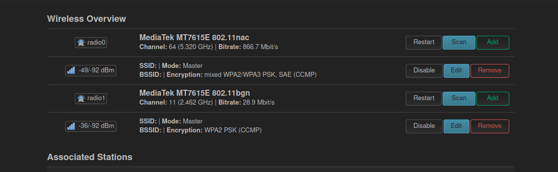
WiFi working from RE650 v2
I was really satisfied that I could make it work. I think I didn’t feel so good in a while about a project that I was doing. Even though for someone who is knees deep in the OpenWrt work, and does all the drivers magic it’s probably trivial, for me it was a great achievement, and I can now confidentially said that I was able to contribute a new device to the list of OpenWrt supported devices
What did I learn
I think the biggest learning lesson is that in the embedded world, following are true
- If prior art exists, make use of it, it’s probably going to be a lot easier.
- Try everything that comes to your mind, as long as there is backup, it doesn’t hurt
- Don’t give up easily, but give yourself breaks. It’s amazing what can you come up with if you just let your body rest and do something totally unrelated.
- That big projects are nothing to be afraid of, but it’s good to start small (I was lucky to start with skeleton ready, I just had to fill in the details) I would have probably gave up long time ago if I had nothing that could guide me through. My attention span is not that great when it comes to such side projects.
- Do a proper research - this one is hard to describe precisely, but it’s good to just go around the code and internet and get a feeling of how people do that stuff. In this case it was going through the commit history and checking how support for similar devices was added and what were the descriptions of commits (they were immensely useful!).
- How to send a patch through
git send-mail- is it how people did it in the old days?