After spending a couple of days laying in my bed with absolute no motivation at all to do anything I’ve decided to do anything that will bring me from the lair of despair.
COVID situation here in Poland at the moment of writing the post is not really great, there is absolutely nothing to do outside because everything is cancelled.
I can either tinker in my “electronic workshop” or do programming which I couldn’t really keep motivation for.
It’s not really only you dear reader whom might have this problem too!
I’ve taken 3 weeks of free vacation to do things I’ve always wanted to do but instead I spent half of it playing games (which I don’t regret!) and half of it… doing absolutely nothing and lying in the bed.
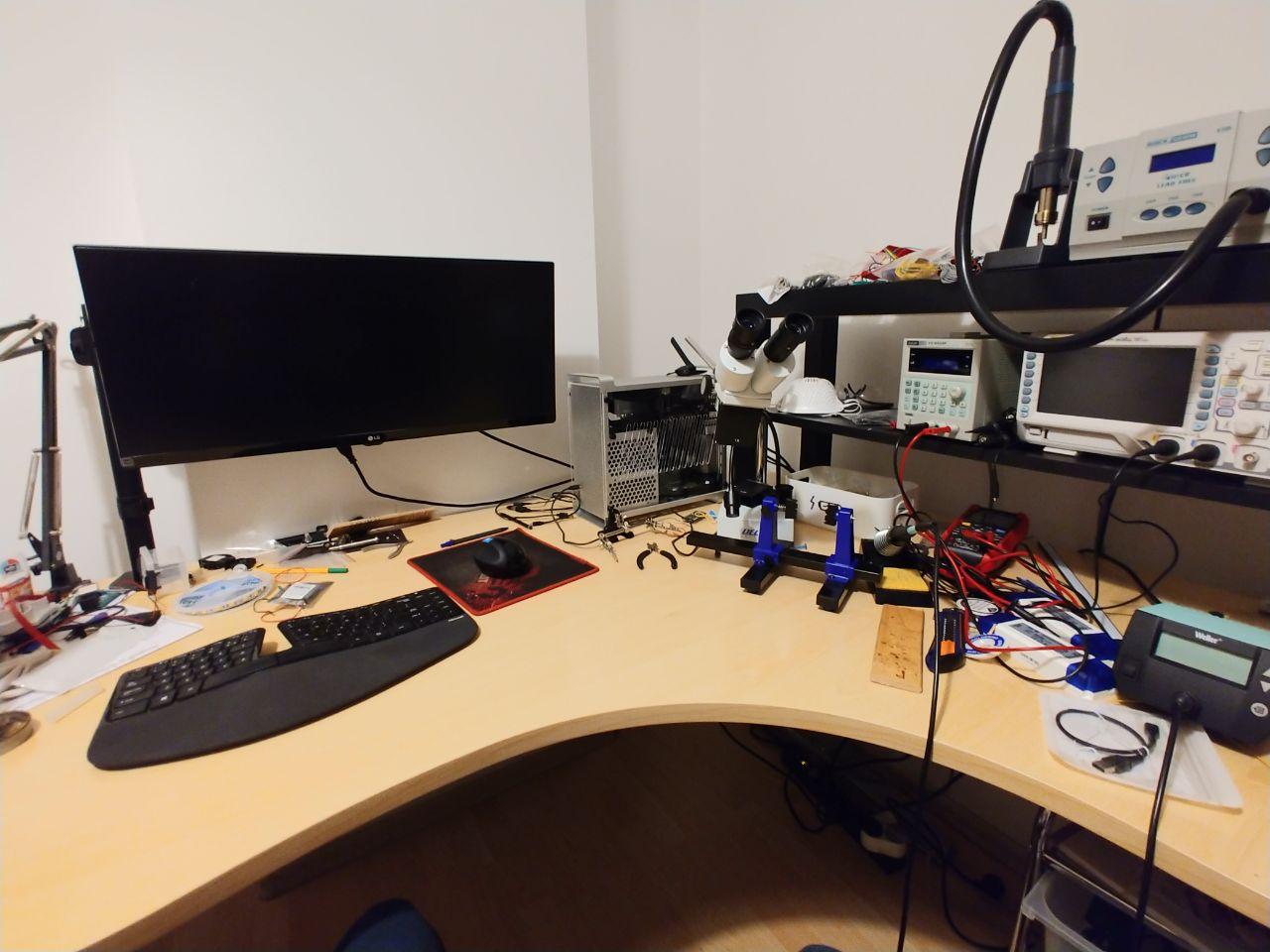
DIY workshop that I've assembled over time
But enough of the depressive kind of things, and let’s dive deep into actual stuff I’ve done.
Constraints
I rent a flat. That means I cannot do anything that is not allowed by the landlord. That includes drilling and making permanent changes. So everything I’m doing needs to be easily reversible or fixable.
Currently I’ve been using Sonoff Mini to control the lights in my room, because switches for them are really far away from the bed and I was always really lazy to shut them off before sleep. So I added smart relay to that. But this only gives me the ability to switch on or off bulbs and the lamps are really positioned badly. Idea came to my mind that I could use double-sided tape and LEDs strips inside LED trough.
Hardware Choices
After having idea in my mind how and where I want to place it it was time to choose the tools.
LED Strips
For LED strip I went with 1200 lumen 5050 60LED per meter. It claimes to be 12W per meter, and cost me around 11 PLN/meter (around $2) so I’ve bought around 7 meters of it.
This strip was dual LED per cell so it had “warm” and cold LED in a single chip. It was wired the same way RGB strips are wired (4 wires) but one of the wires was simple not used.
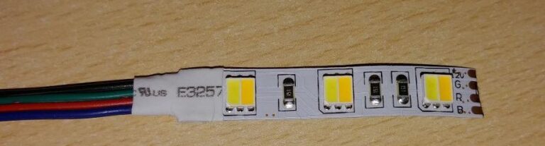
Dual Warm/Cold LED strip
One problem was that the “warm” light of that strip is not really warm as in orange in its maximum setting but more of a white + a tiny bit of green/yellow. On the other hand cold one was actually pretty cold. But I guess I won’t complain about such a cheap strip.
Power Adapter
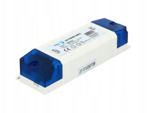
Nothing special. Because I intended to have three sectors of lights, I’ve chosen 12V / 3A in a DIY package. One end you add the AC cable, the other way you got 12V. And it is pretty so you can hide it somewhere invisible. I plan to put it inside a 3D Printed case with controller so all I do is plug the power and connect the LEDs through exposed connectors. But that will come soon (I might write a post about that too!). This one costed me around 25PLN each (~$7)
LED Controller
My only choice for cheap DIY was to either use ESP8266 or ESP32. While ESP8266 is cheaper, and I don’t care about performance in that particular usage I chose to go with ESP32. Reason for choosing ESP32 was that it has built in dedicated PWM support. See related documentation entry on espressif. What that means is that I can set the brightness of the LED through GPIO output of my ESP32.
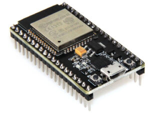
ESP32 NodeMCU v1.1 dev kit
I could’ve done software PWM on ESP8266 but documentation of ESPHome said that it’s preferred to use dedicated PWM hardware instead.
Since I hate flickering of any sort I’ve decided to use dedicated PWM of ESP32 and set the frequency high enough that I won’t see any flicker at all.
BTW I’m talking about this sort of flickering you get when you buy cheap dimmable LEDs on supermarket sale or these LED bulbs mounted to normal light bulbs mount. That is horrible and I can’t stand it. I didn’t even want a chance of it occurring so ESP32 it was
Other stuff
Other than that, I’ve also bought 4 core cable dedicated to soldering to these strips. This is a lot better than wiring it all separately since it will create unbelievable mess if you use single wires for each connection.
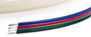
Four core wire
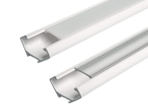
led troughs 45 degree
On PWM Control
For anyone who is familiar with electronics and PWM, just skip it. For anyone else here comes a fast explanation of what PWM means.
PWM is Pulse Width Modulation, that means we use “Width” of the pulse to modulate the signal. Width comes from the fact that if you plug it into the Oscilloscope you will see it exactly as a width of the pulse.
Imagine that you want to power your device with 50% of power. Assuming the device is 12V and it responds linearly to the voltage you give it, you can just power it with 6V and you will have half the power. But changing the voltage is a more complicated. Hence the PWM.
Now imagine you run your device for 10 seconds and its all that matters. Easiest will be to use the light bulb. Power it on for 5 seconds, power it off for 5 seconds and you just powered it using half the power.
But you might say – its not what we wanted! We didn’t want to have it off for half of the time.
So instead of considering the 10 seconds, consider 1 second. power it on for half the second and off for another half and you got 1Hz of PWM modulation.
Speed it up to 2000Hz and you won’t even notice the flickering – and the device will in fact use as much power as you give it using PWM.
This is rather simplified explanation and there are many more things to consider other than mentioned here, but I’m no electronics expert, merely just a hobbyist and this is enough of explanation for me to just use PWM for what I need it to
Failed attempt at running ESP32 with 12V
ESP32 NodeMCU and other dev kit boards have their own Linear Voltage Regulator (AMS1117-3.3) which regulates the power to selected voltage. Since ESP32 is 3.3V powered, when you connect it to 5V USB it uses that regulator to not burn down the chip. For regulating from 5V to 3.3V its not a problem for that tiny chip, given that ESP with GPIO for 2 channels consumes around 150mA.
However if you plug in 12V as I first tried…. well, you basically can run it too, but it will dissipate around (12V – 3.3V) * 0.15A = 2W (see this awesome sparkfun post for how to calculate it) of power into the heat. And after a while it just shorted and burned one of the boards down. I tried to save it by replacing external diode that was not conducting anyhow (I solder-shorted it to test it out) but it seemed to burn down the ESP32 itself. Poor soul.
Preferred way to connect ESP32 to 12V is to either step it down using step-down converters (like this one from pololu) and connect 3.3V output directly to 3.3V input, or step it down to 5V externally and connect it to VIN of the board since 5V to 3.3V conversion is no problem for it.
Using ESPHome for YAML based programming of ESP32
ESPHome is awesome piece of software. Seriously, if you haven’t heard about it go check it out. It basically allows you to write software for ESP using simple declarative YAML for whatever components you want to support in your code.
For my use case, this YAML was enough to get it up and running in no time.
esphome:
  name: curtain_led
  platform: ESP32
  board: nodemcu-32s

wifi:
  ssid: <WiFi name>
  password: <WiFi Password>

mqtt:
  broker: <Broker IP>
  discovery: True

light:
  - platform: cwww
    name: "Curtain LED"
    cold_white: gpio_18
    warm_white: gpio_19
    cold_white_color_temperature: 5500K
    warm_white_color_temperature: 3500K


output:
  - platform: ledc
    pin: GPIO18
    id: gpio_18
    frequency: 2000Hz
  - platform: ledc
    pin: GPIO19
    id: gpio_19
    frequency: 2000Hz
What happened here?
- We define the meta information in esphome block. We need to tell it what board we use and what chip we use so it maps ports and compiles correctly.
- wifi is pretty self-explanatory. We can also configure it to provide a hotspot for configuration so we don’t hardcode the password in the flash but I don’t care about it at this point.
- mqtt is queue used for communication between devices. this is basically where home assistant sends and receives events from/to devices.
- light is definition of our light. Defining the light here is crucial for correct Home Assistant auto-detection. cwww is simply two LED strip with cold/warm LED channels.
- output here we define what ports do what on our board. I defined two PWM outputs and gave them an id that was used in light block. Frequency of PWM here defines the “flicker” of the light if we use PWM for dimming. Anything above 1000-2000Hz should be plenty so that it won’t be visible to your eye.
And that’s it. I now just connect the board to the computer using provided USB, and run esphome <config_name>.yaml run.
This flashes the device with specified configuration. Its really that simple
Wiring the ESP32 to LED strip
Here comes the tricky part (I mean, this is easy concept, but was the hardest of everything previously mentioned).
We need to wire the LED strip in a way that our GPIO turns it on/off with given PWM duty cycle. But we can’t send let’s say 1A of current through our GPIO directly to the LED strip because we will burn our microcontroller down.
For that comes the MOSFET transistor. It allows switching it on/off fast enough, so we can use our PWM signal to switch on/off 12V for the LED strip.
This blog I came across while doing it has greatly helped me understand how to use MOSFET to my advantage. It also gave me an idea to create my own board but that will come later :)
For my application, I’ve used IRL540N MOSFET transistor that I had lying around.
Since I had two channels, I connected two GPIOs to two seperate MOSFETs (to control cold/warm LED independently).
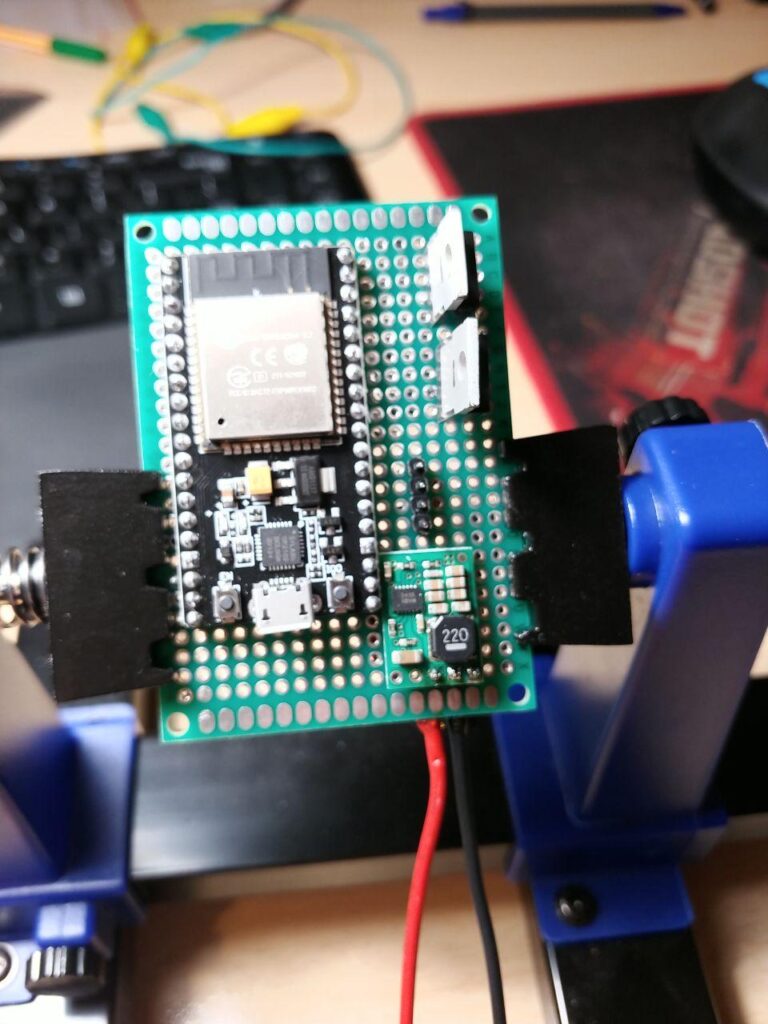
Beautiful board isn't it?
This is really messy on the breadboard, but easy in reality:
- On the left image you can see ESP32, 3.3V buck converter, and two MOSFETs (and 2,54mm connector)
- Top red and black wires provide 12V and GND
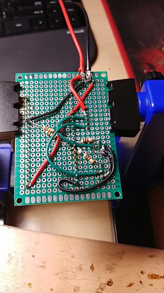
- Two 100Ohm Resistors on the right are used to connect GPIOs to MOSFETs Gate (on the right)
- Same GPIOs are also connected through 20k Ohm to GND to pull it down when it is off. Since the path to MOSFET is low resistance, it doesn’t matter when it on running. But when its off, we don’t want any floating happening hence high resistance path to ground.
- MOSFETs are connected to GND on Drain, and to LEDs warm/cold channel on Source.
- Only thing left on that board is connection of 3.3V output of buck converter to 3.3V IN of the board.
Final result
Images speak for itself.
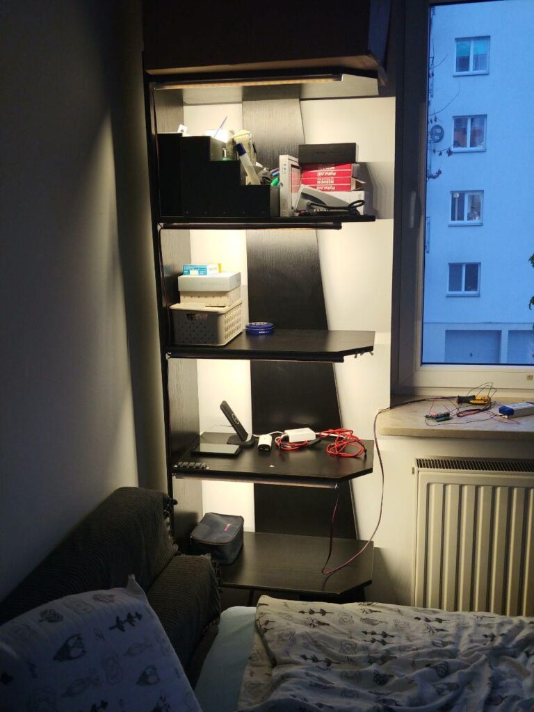
Warm
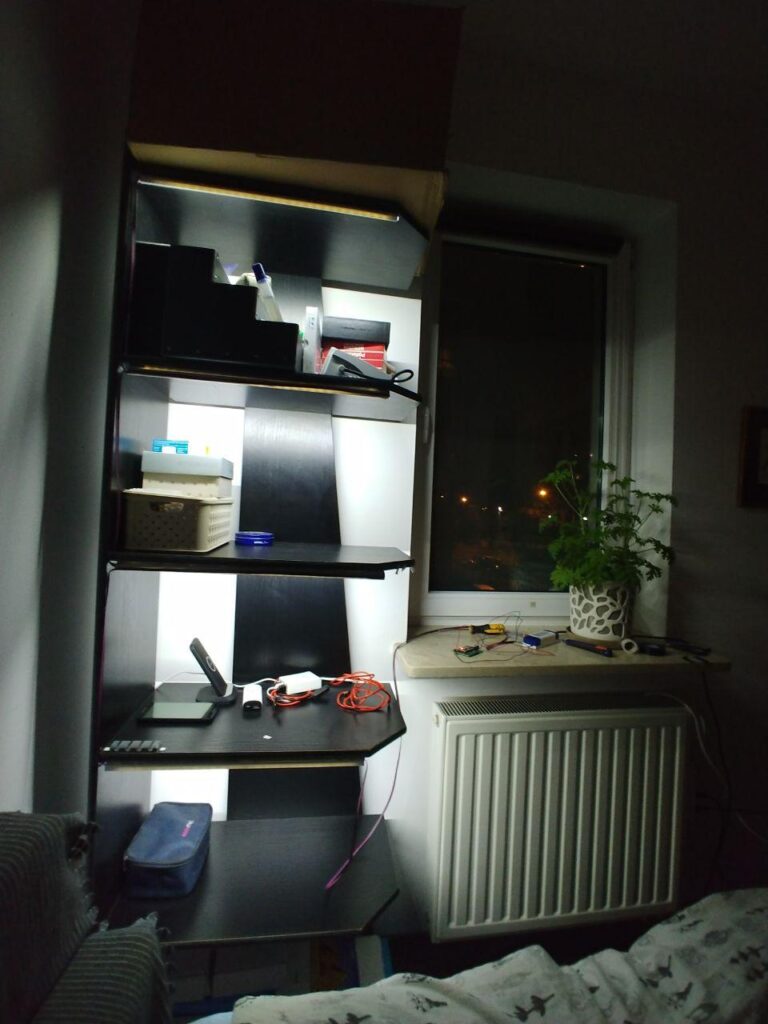
Cold
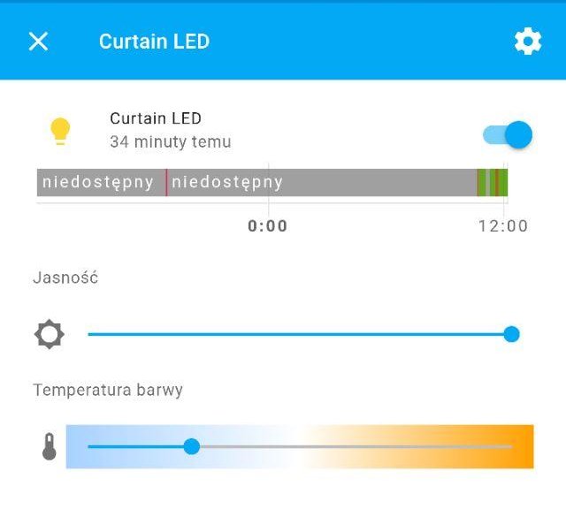
Home Assistant view
This took me 3 days to source the parts and assemble. And also buy another ESP32 after burning it down with 12V :)
Total cost for that single setup I’ve done I estimate to around:
- 20PLN (~$6) for 2m of LEDs
- 40PLN (~$10) for ESP32 dev board (fun fact – ESP32-S2 without dev board in bulk costs 9PLN)
- 30 PLN (~$8,5) for LED mounts and wire
- 5 PLN (~$1.5) for MOSFETs
- Endless ($$$) amount of money from time spent on it.
- Summing it up – it seems to cost around $30 for one controller.
One of the nice things about doing this is that if you direct these LEDs at the ceiling or walls (which in my case are white) – light spreads and diffuses nicely so everything around is also lit. Thanks to that I can sit in a room which is not totally dark, yet has enough light to not cause an eye strain when lying/sitting by the TV/PC.
Summary
This was fun to make. And by fun I mean it actually motivated me to complete it (although I’m not happy with that messy breadboard I made). This is excellent example that sometimes all you need is some variety on what you’re doing.
Even though this lighting was… mostly unnecessary, I could’ve bought just more Yeelight bulbs or just not do it, I’ve decided to do it because I wanted to learn something (understand how MOSFET work!), and it was great time sink for past two-three days.
Next will be designing my own PCB with 12 channels of output for maximum of 4 strips, with integrated power supply all in a single 3D printed box that has connectors for LED strips and connector for AC power.