How does it work without Flannel
Assumption: I’m using host networking through these examples. You could utilize docker network for example, but to make it simple I wanted to stick to the fact below
container network = host/node network
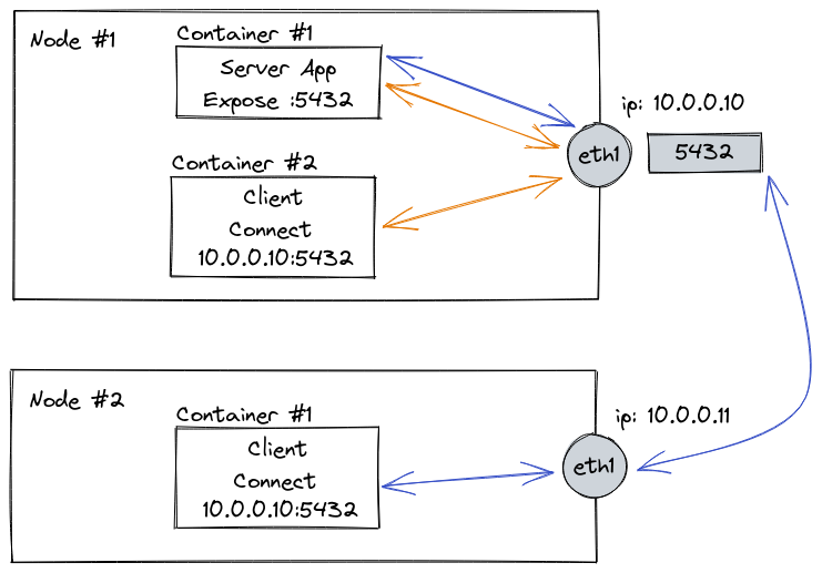
If there was no Flannel, connection between containers would need to happen by directly connecting to the specific port that container is binding to
Like so:
#1 Node 10.0.0.10
- #1 Server Container binds onto port 5432
- #2 Client Container connects to 127.0.0.1:5432 (Orange connection)
#2 Node 10.0.0.11
- #1 Client Container connects to 10.0.0.10:5432 (Blue Connection)
It’s a problem because you have limited amount of ports available for specific interface, and also that you cannot use the same port twice so you would need to keep track of the ports that are used on each node.
You’re also exposing these services to the local area network and this is something we may not want to do.
How to solve it without Flannel
General idea would be to have all containers bind to arbitrary localhost address, and have a tunnel established between nodes. It is possible thanks to the fact we have whole 127.0.0.0/8 address space available (Per RFC 5735)
For example:
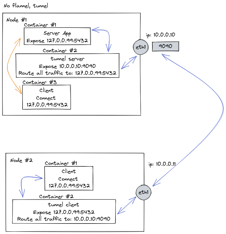
#1 Node 10.0.0.10
- #1 Server Container binds onto port 127.0.0.99:5432
- #2 Tunnel container that accepts connection on 10.0.0.10:9090 and redirects that traffic onto 127.0.0.99:5432
- #3 Client container connects to 127.0.0.99:5432
#2 Node 10.0.0.11
- #1 Tunnel Container that connects to 10.0.0.10:9090 and exposes connection on 127.0.0.99:5432
- #2 Client container connects to 127.0.0.10:5432
What did we solve here?
- Now we don’t bind the container directly to the public facing interface, but instead we create a tunnel
- Assuming the tunnel is created using some kind of Shared Key Encryption, no one will be able to connect / read the traffic unless they have the key too.
- We can bind now arbitrary number of :5432 ports up to 16 milion containers (more than enough)
What problems do we have still?
- We need to create tunnel for each new server
- We could’ve used some kind of smart tunnel (and such solutions exist!) but we’re assuming our tunnel is dumb and just forwards traffic
- We have to handle secrets for each connection to occur
- If we had more than one node we would need to setup the tunnel between each node if on every node we have a client
- That’s pretty inefficient
(Btw concept I just explained is the core idea behind so-called Service Mesh, but this is no way explanation for it)
How flannel solve the problem
Flannel in its default configuration uses so called VXLAN. It setups a one-to-many network on a single port 8472 (IANA specifies that port to be 4789) with routing achieved thanks to Linux built in support for VXLAN.
Testing out in k3d
I’ve used k3d to create testing k3s setup using
k3d cluster create flannel-testing
This creates a cluster with a single node.
Now we can check how is flannel configured on the single node setup. To SSH into the node I use k9s with node-shell configured. Thanks to that I can create shell instance on any node I want and see node’s configuration.
/ # ip route
default via 172.18.0.1 dev eth0
10.42.0.0/24 dev cni0 scope link  src 10.42.0.1
172.18.0.0/16 dev eth0 scope link  src 172.18.0.2
We can see two interfaces - one for eth0 and one for cni0.
Because k3d stands for K3s in Docker we can examine where each interface comes from.
eth0 can be seen in output of docker network ls
> docker network ls
80e3c272a268   k3d-flannel-testing   bridge    local
To see what CIDR it uses we can inspect it using docker network inspect 80e3c272a268
> docker network inspect 80e3c272a268
[...]
"IPAM": {
	"Driver": "default",
	"Options": null,
	"Config": [
		{
			"Subnet": "172.18.0.0/16",
			"Gateway": "172.18.0.1"
		}
	]
},
And this is where eth0 comes from. But where is cni0 defined?
I’d like to find out about it not because I know it’s flannel, but using OS native tooling so this is universal advice.
Turns out it’s not really easy when using busybox image as it doesn’t provide necessary information in ip outputs (doesn’t support -details flag for example). So I need to use different image for that.
So I replaced busybox with nicolaka/netshoot.
Now we can check what is cni0 by typing out
> ip -details link show cni0
cni0: <BROADCAST,MULTICAST,UP,LOWER_UP> mtu 1450 qdisc noqueue state UP mode DEFAULT group default qlen 1000
    link/ether b6:a5:7e:f6:17:25 brd ff:ff:ff:ff:ff:ff promiscuity 0 minmtu 68 maxmtu 65535
	bridge forward_delay [...]
It turns out cni0 is not a VXLAN interface? Where is our vxlan interface?
> ip link show
1: lo: [..]
2: flannel.1: <BROADCAST,MULTICAST,UP,LOWER_UP> mtu 1450 qdisc noqueue state UNKNOWN mode DEFAULT group default
    link/ether 12:c0:9a:88:11:82 brd ff:ff:ff:ff:ff:ff
3: cni0: <BROADCAST,MULTICAST,UP,LOWER_UP> mtu 1450 qdisc noqueue state UP mode DEFAULT group default qlen 1000
    link/ether b6:a5:7e:f6:17:25 brd ff:ff:ff:ff:ff:ff
5: vethf2772684@if3: <BROADCAST,MULTICAST,UP,LOWER_UP> mtu 1450 qdisc noqueue master cni0 state UP mode DEFAULT group default
    link/ether 42:c1:fd:fe:42:e5 brd ff:ff:ff:ff:ff:ff link-netnsid 2
7: vethf314b245@if3: <BROADCAST,MULTICAST,UP,LOWER_UP> mtu 1450 qdisc noqueue master cni0 state UP mode DEFAULT group default
    link/ether 52:2b:6e:1b:66:61 brd ff:ff:ff:ff:ff:ff link-netnsid 4
8: veth2cd71447@if3: <BROADCAST,MULTICAST,UP,LOWER_UP> mtu 1450 qdisc noqueue master cni0 state UP mode DEFAULT group default
    link/ether d2:e1:b3:06:8a:ed brd ff:ff:ff:ff:ff:ff link-netnsid 5
9: eth0@if10: <BROADCAST,MULTICAST,UP,LOWER_UP> mtu 1500 qdisc noqueue state UP mode DEFAULT group default
    link/ether 02:42:ac:12:00:02 brd ff:ff:ff:ff:ff:ff link-netnsid 0
10: veth86f7911b@if3: <BROADCAST,MULTICAST,UP,LOWER_UP> mtu 1450 qdisc noqueue master cni0 state UP mode DEFAULT group default
    link/ether be:4e:7b:f5:8c:12 brd ff:ff:ff:ff:ff:ff link-netnsid 1
11: vethd2d58b32@if3: <BROADCAST,MULTICAST,UP,LOWER_UP> mtu 1450 qdisc noqueue master cni0 state UP mode DEFAULT group default
    link/ether f6:2a:73:93:e9:ca brd ff:ff:ff:ff:ff:ff link-netnsid 6
There are plenty of interfaces! We can probably guess now which do we want to check next.
> ip -details link show flannel.1
2: flannel.1: <BROADCAST,MULTICAST,UP,LOWER_UP> mtu 1450 qdisc noqueue state UNKNOWN mode DEFAULT group default
    link/ether 12:c0:9a:88:11:82 brd ff:ff:ff:ff:ff:ff promiscuity 0 minmtu 68 maxmtu 65535
    vxlan id 1 local 172.18.0.2 dev eth0 srcport 0 0 dstport 8472 nolearning ttl auto ageing 300 [...]
(I’m cutting the output a little using [...])
Ah! There is our VXLAN interface. Now how does the traffic from flannel.1 interface land in our cni0 interface?
According to information found in this amazing article it is achieved by forwarding data using iptables from the bridge to the vxlan interface and vice versa.
So in short, there are two interfaces - flannel.1 which acts as virtual lan for our network of nodes, and cni0 which acts as a bridge between containers and virtual lan.
Each container in single node gets its own IP, and all these IPs are bridged using cni0 network.
We can see that here after we check the definition of cni0 bridge
> brctl show
bridge name	bridge id		STP enabled	interfaces
cni0		8000.b6a57ef61725	no		veth2cd71447
							            veth86f7911b
							            vethd2d58b32
							            vethf2772684
							            vethf314b245
Every veth found in this bridge is a container on our node. Each of them has its own IP.
Multi-node k3d cluster
So far we have analyzed what is configured on a single-node setup and how flannel looks like from that perspective.
I’ve created another cluster with 3 nodes, to see how different the routing table is. And boy it is.
> route -n
Kernel IP routing table
Destination     Gateway         Genmask         Flags Metric Ref    Use Iface
0.0.0.0         172.19.0.1      0.0.0.0         UG    0      0        0 eth0
10.42.0.0       10.42.0.0       255.255.255.0   UG    0      0        0 flannel.1
10.42.1.0       0.0.0.0         255.255.255.0   U     0      0        0 cni0
10.42.2.0       10.42.2.0       255.255.255.0   UG    0      0        0 flannel.1
172.19.0.0      0.0.0.0         255.255.0.0     U     0      0        0 eth0
- 10.42.0.0, 10.42.1.0, 10.42.2.0 are all networks of nodes. For every new node we have a new route configured on every other node so that every node knows where to find each other.
- Containers are assigned IPs from the 10.42.N.0/24 range, that is from 10.42.N.1 through 10.42.N.254 Ips.
- We can spot an obvious limitation to that - we can only have at most 254 hosts on a single node.
- Another limitation is number of nodes - this is the same 254 limit as for pods.
Flow chart of flannel
So to follow the analogy from the previous ideas, we can draw following flow chart.
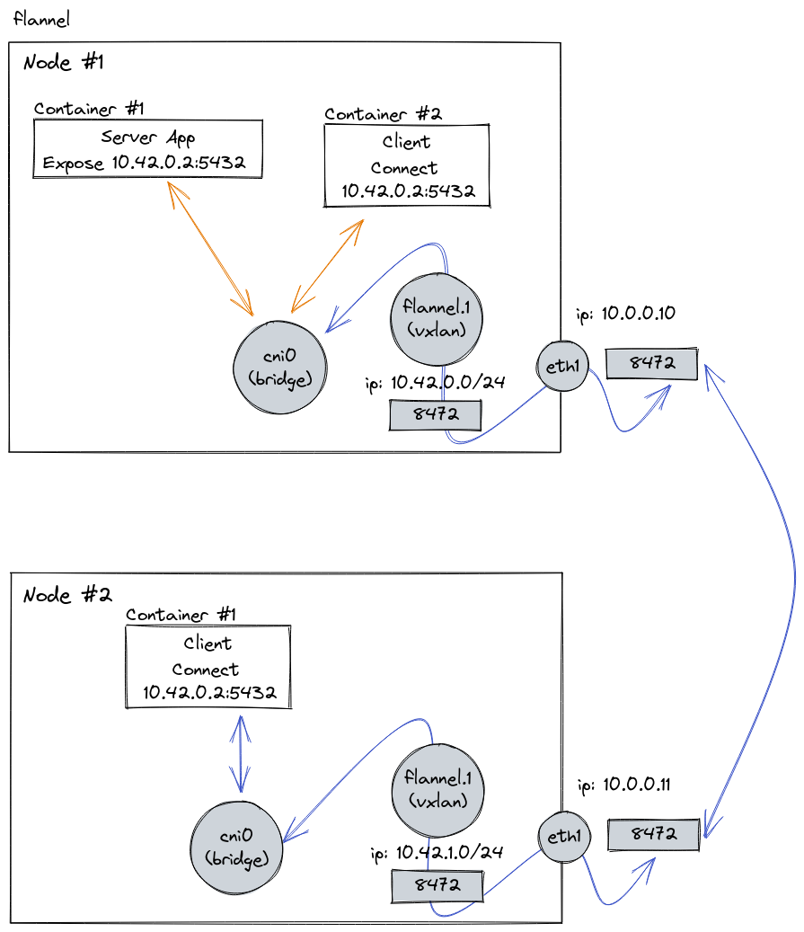
Allow me to not draw arrows through every interface as that was too cluttered. Let’s for simplification sake assume that it flows through all interfaces the arrow crosses
What flannel solves for us
So by looking at above diagram it should be pretty clear why do we use flannel as networking interface:
- Each container gets its own IP address from the pool of 10.42.0.0/24
- Each node gets a pool of IP addresses from the range of 10.42.0.0/24 to 10.42.255.0/24.
- All inter-container traffic is handled through a single port of VXLAN
- IPs and routing is setup automatically (that’s the job of flannel - to read the config from each node and configure its routing tables)
What default configuration of flannel doesn’t solve
Traffic IS NOT encrypted between nodes, that means if there is someone in the same switching domain that your nodes are, they can listen to the traffic happening between them and be able to read it out. Assuming of course that you don’t use encrypted protocol like HTTPS.
To solve that problem you could use different tunneling technique like ipsec or wireguard per documentation on rancher website
Additional resources
These resources were helpful in understanding what flannel does: